Moving Beyond Guesswork: Design Principles That Align with Plumbing Codes and Natural Flow Dynamics
Imagine turning on your kitchen faucet and hearing only the smooth rush of water—not a gurgle from the nearby sink. Picture flushing a toilet with consistent performance while the shower drain nearby remains silent and odor-free. This isn’t plumbing magic; it’s the result of a thoughtfully engineered drain-waste-vent (DWV) system operating in harmony with physics and established code principles. In this comprehensive guide, we translate complex plumbing concepts into an accessible, step-by-step framework grounded in International Plumbing Code (IPC) and Uniform Plumbing Code (UPC) standards. Whether you’re planning a bathroom update, evaluating a renovation proposal, or seeking to understand the hidden infrastructure protecting your home’s health, this resource provides clear, actionable guidance for designing systems that function reliably over the long term.
Introduction: Why Your Drain System Is More Than Just Pipes
Beneath floors and behind walls lies a critical home system: the drain-waste-vent (DWV) network. Often unnoticed until issues arise, this system performs two interdependent functions. First, it transports wastewater and solids safely away from fixtures to the main sewer or septic line using gravity. Second, it maintains balanced air pressure throughout the network via dedicated venting, preserving the water seals in P-traps that block sewer gases from entering living spaces. When either function is compromised, consequences may follow: slow drainage, disruptive gurgling, persistent odors, or potential exposure to hazardous gases.
Many approach drain projects with fragmented understanding—focusing solely on pipe slope while overlooking vent placement, or installing traps without verifying vent proximity. This piecemeal strategy ignores the system’s inherent interdependence. A clog may stem not from debris alone but from inadequate venting causing airlock. A sewer smell might originate from a vent installed too close to an opening or improperly sized for the drainage load. Current resources often exacerbate confusion: oversimplified diagrams lacking code context, or overly technical documents without practical translation. Inspection observations frequently note recurring issues: vents placed beyond maximum trap-arm distance, insufficient slope on horizontal runs, or inaccessible cleanouts—challenges preventable with foundational knowledge.
This guide bridges that gap. Built upon analysis of plumbing code standards, engineering principles, and documented field patterns, we present the Flow Integrity Framework—a three-layer methodology transforming drain and vent design from uncertainty into a logical, repeatable process. We emphasize the essential “why” behind requirements, empowering informed decisions whether sketching a single bathroom group or evaluating a whole-house system. Understanding these principles supports resilient infrastructure, helps prevent avoidable repairs, safeguards indoor air quality, and contributes to consistent fixture performance. Let’s begin by establishing the non-negotiable foundation upon which reliable designs are built.
The Flow Integrity Framework: Three Layers to Support Waste Flow
At its core, a DWV system operates on consistent physical principles. Water flows downhill. Air seeks equilibrium. Sewer gases follow pressure differentials. The Flow Integrity Framework translates these principles into a structured design approach through three interlocking layers. Master each layer sequentially to cultivate diagnostic awareness. Skip or weaken any layer, and system vulnerability increases. This framework addresses recurring gaps observed across residential plumbing contexts—from new construction details to renovation constraints.
The Fundamental Principle: A drain system moves waste by gravity; a vent system maintains atmospheric pressure to let gravity work unimpeded. Compromise the vent path, and drainage performance suffers. Protect the trap seal, and you protect indoor air quality.
Layer 1: The Physics Foundation – How Waste Really Moves
Before consulting code tables, internalize the physics governing wastewater movement. This layer explains the “why” behind requirements, transforming measurements into logical safeguards. Without this understanding, rules feel arbitrary. With it, they become intuitive design guides.
Gravity Flow Dynamics: It’s Not Just “Downhill”
Wastewater flows as a moving column where liquid and solids travel within a film of water along the pipe interior. Simultaneously, air must flow opposite to the water—upward through the same pipe—to replace displaced volume. Imagine drinking a thick beverage through a straw: seal the top after drawing liquid up, and flow stops. Similarly, without adequate air replacement behind draining water, negative pressure (partial vacuum) develops downstream. This vacuum may siphon water from nearby P-traps, breaking the seal that blocks sewer gases. Conversely, when a large volume of water (like a toilet flush) rushes down a stack, it compresses air ahead of it. Without a vent path for this pressurized air to escape, it forces its way through the nearest trap—causing gurgling sounds and potentially displacing trap water. This push-pull of air pressure governs DWV behavior.
The Trap Seal: Your Home’s Essential Barrier
Every fixture connects via a trap—a U-, S-, or P-shaped bend holding 1.5 to 2 inches of water. This water barrier is the primary defense against methane, hydrogen sulfide, and other gases produced in sewer lines. Physics dictates this seal’s vulnerability:
– Siphonage: Rapid drainage downstream creates suction that pulls water from the trap.
– Blowout: Compressed air from an upstream surge forces water out of the trap.
– Evaporation: In infrequently used fixtures (guest bathroom sinks, floor drains), standing water slowly evaporates, breaking the seal over time.
– Capillary Action: A single strand of hair or thread bridging the trap arm can wick water out gradually.
The vent system exists primarily to protect this seal. By providing an air pathway connected between the trap and fixture outlet, vents equalize pressure fluctuations. When water drains, air enters through the vent; when water surges, excess air escapes upward. The trap seal remains stable. This is why vent placement relative to the trap is critical—it vents the trap, not merely the fixture.
The Critical Role of Slope: Balance Over Steepness
Common intuition suggests steeper pipes drain faster. In DWV systems, this is often counterproductive. Code-mandated slopes (typically 1/4 inch per foot for pipes 2.5 inches and smaller, 1/8 inch per foot for 3 inches and larger) serve two precise purposes:
1. Maintain Scouring Velocity: Water must flow fast enough (approximately 2–3 feet per second) to carry solids without deposition. Too shallow a slope causes waste to settle, increasing clog risk.
2. Preserve the Air Core: Proper slope ensures wastewater flows as a thin film along the bottom 50–75% of the pipe diameter, leaving the upper portion clear for air movement. Excessive slope causes water to “run away” from solids, stranding them. It may also accelerate flow enough to create vacuum effects behind the water column—increasing siphonage risk on connected traps. Think of a mountain stream versus a gentle river: the stream’s speed erodes its banks; the river’s steady flow carries sediment smoothly. Drain pipes benefit from river-like flow.
Illustrative Physics Scenario:
A homeowner installs a new basement bathroom. The shower drain slopes at 1/2 inch per foot (twice the typical requirement for a 2-inch pipe) to “ensure fast drainage.” Initially functional, the toilet begins gurgling when the shower runs within several months. Why? The excessively steep slope accelerated water flow, creating strong negative pressure downstream. This suction pulled air—and eventually water—through the toilet’s trap, compromising its seal. The solution involved correcting the slope and verifying vent placement relative to both fixtures. Physics, not pipe size alone, was the contributing factor.
Layer 2: Code Compliance – Translating Physics into Actionable Guidelines
Physics provides the “why”; plumbing codes provide the measurable “how.” In the United States, two model codes are widely referenced: the International Plumbing Code (IPC) published by the International Code Council (ICC), and the Uniform Plumbing Code (UPC) published by the International Association of Plumbing and Mechanical Officials (IAPMO). Most jurisdictions adopt one or the other, often with local amendments. Your essential first step before designing any system: Contact your local building department to confirm the enforced code edition and obtain amendment documents. Never assume national standards apply uniformly—coastal regions may require seismic bracing; cold climates mandate deeper frost-line considerations for cleanouts; historic districts may restrict materials.
While nuances exist between IPC and UPC, core DWV principles remain consistent. Codes codify lessons learned from documented field experiences. Each measurement, distance, and material specification addresses a recognized challenge. Understanding the intent behind rules supports better application than rote memorization.
Decoding Fixture Units: The Language of Drainage Load
Codes size pipes using Drainage Fixture Units (DFUs)—a standardized measure of a fixture’s probable hydraulic load and usage frequency. One DFU represents the load of a single lavatory sink (baseline). Fixtures with higher flow rates or solids content carry higher DFU values. Why? A toilet’s sudden surge creates different hydraulic stress than a slow-draining bathtub. DFUs allow accurate calculation of cumulative demand on branch lines and stacks.
Table: Standard DFU Values for Common Residential Fixtures (IPC Table 709.1 / UPC Table 7-1)
| Fixture Type | DFU Value (IPC) | DFU Value (UPC) | Notes |
|————–|—————–|—————–|——-|
| Lavatory Sink | 1.0 | 1.0 | Standard bathroom sink |
| Kitchen Sink (1 or 2 bowls) | 2.0 | 2.0 | Includes dishwasher connection |
| Bathtub or Shower | 2.0 | 2.0 | Shower stall equivalent to tub |
| Toilet (1.6 gal or less) | 4.0 | 3.0 | Note IPC/UPC difference |
| Toilet (older >1.6 gal) | 5.0 | 4.0 | Verify local allowances |
| Washing Machine (residential) | 2.0 | 2.0 | Requires indirect drain receptor |
| Floor Drain (2″) | 2.0 | 2.0 | Common in basements, garages |
| Dishwasher | 2.0 | 1.0 | Counts separately if not tied to sink |
| Bidet | 1.0 | 1.0 | — |
| Total for Standard Bathroom Group | 8.0 | 7.0 | Sink (1) + Tub (2) + Toilet (4/3) + Bidet (1) |
Practical Application: When designing a new bathroom, sum DFUs for all fixtures draining into a common branch line. A standard group totals 7–8 DFUs. Per IPC Table 710.1(1), a horizontal branch serving ≤ 8 DFUs requires a minimum 2-inch pipe. Exceeding 8 DFUs (e.g., adding a second sink) typically requires increasing to 3 inches. Misjudging DFUs may lead to undersized pipes—increasing the likelihood of slow drainage under normal use. Always calculate DFUs before selecting pipe diameters.
Vent Placement: The Trap Arm Distance Rule
This is frequently cited in field observations. The horizontal pipe segment between a fixture’s trap outlet and the vent connection point is the trap arm. Codes limit its length to prevent pressure fluctuations from affecting the trap seal before air can enter via the vent. Maximum allowable length depends on pipe diameter and slope:
Table: Maximum Trap Arm Length (IPC Table 906.1 / UPC Table 10-1)
| Trap Size (Inches) | Pipe Slope | Max Horizontal Length (Inches) | Practical Note |
|——————–|————|——————————-|—————-|
| 1.25″ (Lavatory) | 1/4″ per ft | 30″ | Measure carefully under vanities |
| 1.5″ (Kitchen Sink) | 1/4″ per ft | 42″ | From trap outlet to vent tee |
| 2″ (Toilet, Shower) | 1/4″ per ft | 60″ | Common focal point for verification |
| 2″ (Toilet, Shower) | 1/8″ per ft | 48″ | UPC often requires steeper slope |
| 3″ (Toilet only) | 1/8″ per ft | 72″ | Less common in branch lines |
Application Insight: Installing a toilet 5 feet (60 inches) from the main stack? If the toilet connects directly to a 3-inch stack without a separate vent between trap and stack, the trap arm length is 60 inches. For a 2-inch trap arm (common with many toilets), this may exceed UPC limits at 1/8″ slope. Solution: Install a vent tee within the maximum allowable distance of the trap outlet. Never assume “close enough” suffices—field measurements matter. This rule exists because pressure changes propagate through water columns at measurable speeds; beyond specified distances, the trap seal may destabilize before vent air compensates.
Vent Sizing and Termination: Beyond the Roof Penetration
Vents form a continuous network sized to handle air displacement without restriction. Key considerations:
– Minimum Vent Diameter: Never less than 1.25 inches (IPC 904.3), though typically matches the drain pipe it serves up to 3 inches. A 3-inch building drain generally requires at least a 1.5-inch vent stack.
– Roof Termination Height: Must extend at least 6 inches above the roof surface (IPC 904.4). In snow-prone areas, extend higher to prevent blockage.
– Proximity to Openings: Vents must terminate at least 10 feet horizontally from windows, doors, or air intakes unless extended 3 feet above that opening (IPC 904.6). Sewer gases are denser than air and may drift downward.
– Cold Climate Consideration: In regions with sustained freezing temperatures (Climate Zones 5+ per IECC), vents 2 inches or smaller may require heat tape, increased diameter (e.g., 3-inch vent near termination), or insulation to reduce frost closure risk—a documented cause of seasonal drainage issues.
– IPC vs. UPC Note: UPC Section 907 generally restricts Air Admittance Valves (AAVs) in residential settings except under specific engineered conditions. IPC Section 918 permits AAVs with constraints (e.g., not for main vent stacks, must be accessible). Verify local adoption. Never install assuming universal permission.
Cleanout Requirements: Planning for Future Access
Codes require cleanouts at strategic points to enable maintenance without destructive access. Overlooking these creates future challenges:
– Building Drain Cleanout: Required within 5 feet of the foundation wall where the drain exits (IPC 708.1.1). Must remain accessible—never buried under concrete without a cleanout box.
– Stack Cleanouts: Required at the base of every soil stack (vertical drain carrying water closet waste) and at intervals in multi-story buildings.
– Direction Changes: Required where a horizontal drain changes direction by more than 45 degrees.
– Fixture Groups: Recommended (and often required) for clusters like bathroom groups. A single cleanout serving multiple fixtures simplifies clearing blockages affecting that zone.
– Material Note: Cleanout plugs should match pipe material (PVC plug in PVC fitting). Avoid dissimilar materials that may seize or corrode.
Layer 2 transforms physics into measurable criteria. These guidelines reflect documented solutions to historical challenges. When you recognize that the 60-inch trap arm limit correlates with pressure wave behavior in water columns, compliance shifts from obligation to logical design choice. This understanding becomes a diagnostic lens for evaluating existing systems or troubleshooting performance.
Layer 3: Practical Implementation – From Plan to Durable Execution
Theory and code converge during physical installation. Layer 3 addresses material selection, tool considerations, sequencing, and adaptable techniques that support long-term performance. Precision here reduces the likelihood of future service needs.
Material Selection: Choosing Appropriately for Context
PVC (Schedule 40) is common in modern residential DWV systems due to cost, ease of installation, and corrosion resistance. Understanding material properties prevents mismatched applications. Never substitute based solely on availability without verifying code compliance and suitability.
Table: DWV Pipe Material Considerations
| Material | Typical Applications | Important Limitations | Installation Notes |
|———-|———————-|————————|——————-|
| PVC (Schedule 40) | Interior drains, vents, cleanouts | Degrades in UV light; not for hot water | Use primer + PVC cement per ASTM standards; support every 4 ft horizontally |
| ABS | Cold climates (impact resistance) | Banned in some jurisdictions; UV-sensitive | Use ABS-specific cement; distinct black color |
| Cast Iron | Stack noise reduction; fire-rated assemblies | Heavy; requires mechanical joints; costly | Support at every floor; use no-hub couplings for repairs |
| Chromed Brass | Exposed trap arms (vanities, kitchens) | Not for concealed runs; higher cost | Sweat or compression fittings; verify slope |
| PEX or Similar Flexible Tubing | Not approved for DWV | Lacks rigidity, smooth bore, code listing | Never use for drain, waste, or vent applications |
Critical Joining Insight: PVC and ABS cements create solvent welds, chemically fusing pipe and fitting. Skipping primer (required for PVC per ASTM D2855) may leave microscopic gaps. Applying cement to only the pipe (not the socket) creates weak joints. Recommended sequence:
1. Dry-fit components; mark alignment.
2. Apply primer to pipe end and socket (PVC only).
3. Apply cement liberally to both surfaces.
4. Insert pipe fully with a slight twist; hold 30 seconds.
5. Wipe excess immediately.
6. Allow full cure time before pressure testing or use (follow product guidelines).
Illustrative Material Scenario: A installer uses an adhesive not formulated for PVC to join a vent tee. Initially leak-free, vibration gradually weakens the bond. Months later, a pressure fluctuation separates the joint inside a wall. By the time moisture is visible below, structural damage has occurred. Proper solvent welding creates a permanent, vibration-resistant seal. Adhesive selection matters.
Tool Considerations: Supporting Precision
Reliable results benefit from appropriate tools:
– Pipe Cutter (Ratcheting): Creates square, burr-free cuts essential for leak-free joints. Hacksaw cuts often leave burrs that disrupt flow.
– Deburring Tool: Removes internal ridges after cutting—critical for maintaining smooth bore.
– Levels with Slope Indicators: Laser levels project slope lines; torpedo levels with slope vials (1/4″ or 1/8″ per foot) verify pitch during installation.
– Inspection Camera (20+ ft): Verifies cleanout access, checks for existing obstructions pre-installation, and documents work.
– Pipe Supports: Metal hangers (not wire) spaced per code: every 4 feet for horizontal runs, at every floor for vertical stacks. Unsupported pipes may sag over time, creating low spots where waste accumulates.
A Step-by-Step Design Sequence: Building Confidence Through Order
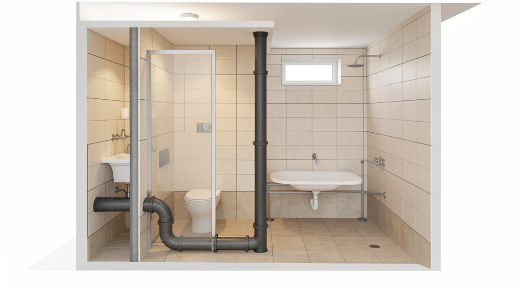
Follow this sequence thoughtfully. Skipping steps may create compounding issues. We’ll walk through designing a typical second-floor bathroom group (toilet, lavatory, shower) as a concrete example.
Step 1: Map Every Fixture and Its Drainage Requirements
Begin with a scaled floor plan sketch. Mark exact fixture locations, wall studs, floor joists, and the nearest existing stack or main drain access point. Note structural obstacles: HVAC ducts, electrical panels, load-bearing walls. For each fixture, record:
– Fixture type
– Trap size (typically 1.5″ for lavatory, 2″ for shower/toilet)
– Drain outlet location
– Distance to proposed vent connection point
Example Bathroom Group Sketch Notes:
– Toilet: Centered 12″ from finished wall. Trap arm runs left toward stack.
– Lavatory: Vanity centered on wall. Trap arm runs down through floor.
– Shower: Curbless design. Drain centered in 36″x36″ area. Trap arm runs right.
– Existing 3″ soil stack located in adjacent closet wall, 48″ from toilet location.
– Floor joists run perpendicular to stack direction (requires notching or sistering consideration).
Step 2: Calculate Total Drainage Fixture Units (DFUs)
Sum DFUs for all fixtures draining into the proposed branch line:
– Toilet (1.6 gal): 4.0 DFU (IPC) / 3.0 DFU (UPC)
– Lavatory Sink: 1.0 DFU
– Shower: 2.0 DFU
– Total Branch Load: 7.0 DFU (IPC) / 6.0 DFU (UPC)
Design Decision: Per IPC Table 710.1(1), a horizontal branch serving ≤ 8 DFUs requires minimum 2-inch pipe. UPC allows 2-inch pipe for ≤ 8 DFUs. Branch line diameter = 2 inches. Verify local requirements for toilet drain size—some jurisdictions specify 3-inch for toilets regardless of DFU.
Step 3: Design the Drain Layout with Correct Slope
Starting at the fixture farthest from the stack (shower), calculate required drop:
– Shower to Lavatory distance: 60 inches
– Required slope for 2-inch pipe: 1/4 inch per foot = 0.0208 inches per inch
– Total drop needed: 60″ × 0.0208 = 1.25 inches
– Lavatory to Toilet distance: 48 inches
– Drop needed: 48″ × 0.0208 = 1 inch
– Toilet to Stack connection: 24 inches
– Drop needed: 24″ × 0.0208 = 0.5 inches
– Total cumulative drop from shower to stack: 2.75 inches
Practical Slope Verification:
1. Establish reference height at shower drain location (e.g., subfloor level = 0″).
2. Shower trap arm outlet height = trap depth (typically ~2″).
3. At lavatory location (60″ away), pipe elevation = 2″ – 1.25″ = 0.75″ above subfloor.
4. At toilet location (108″ from shower), elevation = 2″ – 2.25″ = -0.25″ (0.25″ below subfloor—requires framing adjustment).
5. At stack connection (132″ from shower), elevation = 2″ – 2.75″ = -0.75″.
Critical Slope Check: Measure actual joist depth. Standard 2×10 joists provide ~9.25″ depth. With 0.75″ drop needed at stack connection, verify pipe fits within joist cavity without compromising structure. If not, consider:
– Sistering joists to create a lowered section
– Running pipe through notched joists (max notch depth = 1/6 joist depth per IRC R502.8.1)
– Using a shallower slope (1/8″ per foot) if code permits for this run length and DFU load (verify!)
Common Slope Note: Slope must be consistent along each straight segment. Changes in direction require re-establishing slope from the new high point. Verify pitch at every joint during installation.
Step 4: Integrate the Vent System – Types and Placement
Apply the trap arm distance rule carefully:
– Shower Trap Arm: Max length 60″ at 1/4″ slope (IPC). Distance to proposed vent tee = 42″. Compliant.
– Lavatory Trap Arm: Max length 42″ at 1/4″ slope. Distance to vent tee = 18″. Compliant.
– Toilet Trap Arm: Max length 60″ at 1/4″ slope. Distance to stack (acting as vent) = 24″. Compliant.
Vent Configuration Options:
– Option A (Wet Vent): A single pipe functions as drain for upstream fixtures and vent for others. IPC permits wet venting for bathroom groups within specific DFU limits (≤ 6 DFU on the wet-vented section). Total branch DFU = 7.0 (IPC), exceeding this limit. Option A may not comply under IPC.
– Option B (Individual Fixture Vents): Separate vent pipes from each fixture’s trap arm to a common vent stack. Requires more materials but is widely compliant.
– Option C (Circuit Vent): A single horizontal vent pipe connects multiple fixture traps, rising vertically at the branch end. Efficient for multiple fixtures in line but may be excessive for a single bathroom group.
Selected Approach for Example: Option B (Individual Vents) due to IPC DFU constraints on wet venting. Lavatory vent (1.5″) rises within vanity wall. Shower vent (1.5″) rises within shower curb wall. Both tie into a new 2-inch vent stack running vertically in the closet wall alongside the soil stack. Toilet connects directly to the 3-inch soil stack, which is already vented above the roof.
Vent Termination Detail: The new 2-inch vent stack extends through the roof. Flashing is installed per roofing standards. Pipe extends 12 inches above roof surface (exceeding 6-inch minimum for snow consideration). Termination point is 15 feet horizontally from nearest bedroom window—compliant without additional height. A screened cap prevents debris and insect entry while allowing airflow.
Step 5: Confirm Pipe Sizing Against Load
Verify all diameters against DFU calculations and code tables:
– Fixture Trap Arms: Lavatory = 1.5″, Shower = 2″, Toilet = 3″ (per local requirement)
– Horizontal Branch (serving all three): 2″ (handles ≤ 8 DFU per IPC Table 710.1(1))
– Soil Stack (existing): 3″ (adequate for one bathroom group; verify total house load)
– New Vent Stack: 2″ (minimum size for venting multiple fixtures; IPC 904.3)
– Building Drain (existing): 4″ (standard for single-family homes; verify with total house DFUs)
Note on Oversizing: Installing a 3-inch pipe for a 2-inch branch line may seem cautious but can reduce flow velocity, failing to scour pipe walls and allowing buildup. It also increases material use and installation complexity. Stick to code-minimum sizes unless DFU calculations explicitly require larger. Precision supports performance.
Step 6: Plan for Cleanouts and Accessibility
Strategic cleanout placement supports future maintenance:
– Install a 2-inch cleanout plug at the end of the horizontal branch line, just before it connects to the soil stack. Position behind a removable closet panel.
– Include a cleanout at the base of the new vent stack where it ties into the main vent system (if accessible in basement).
– Verify the building drain cleanout exists within 5 feet of the foundation wall exit point. If renovating, add a cleanout box if none exists.
– Practical Tip: Install cleanouts with the plug facing an accessible direction (not toward a stud). Use plugs with square drive heads for easier future removal. Document cleanout locations on an “as-built” diagram stored with home records.
Step 7: Finalize Documentation and Seek Verification
Before installation:
1. Draw a simple isometric diagram showing pipes, slopes, fixtures, vents, and cleanouts.
2. Annotate with pipe sizes, slopes, and DFU calculations.
3. Submit to local building department for permit review.
4. Schedule required inspections: rough-in (before walls close), final (after fixture installation).
5. Recommended Step: Discuss the design with a licensed plumber. Many offer brief consultations at minimal cost compared to correcting errors post-installation. Field experience may identify nuances diagrams miss—like interference with attic insulation baffles or access panel conflicts.
This sequence builds confidence through logical progression. Each decision rests on the previous layer, with physics and code as consistent references. When constraints arise—like a beam blocking the ideal path—evaluate solutions against the framework: “Does this maintain proper slope? Does it preserve trap arm distances? Does it comply with vent sizing?” The framework provides criteria for sound judgment.
Navigating Common Challenges and Contextual Considerations
Real-world installations rarely match ideal diagrams. Framing conflicts, existing infrastructure, and spatial constraints require adaptable solutions grounded in principle. This section addresses frequent scenarios with actionable strategies, emphasizing why certain approaches align with system integrity.
Retrofitting Vents in Finished Spaces: Code-Compliant Pathways
Adding fixtures to existing homes often requires running vents through finished walls or ceilings. Avoid these pitfalls:
– Pitfall: Running a vent pipe horizontally through attic insulation without support. Potential Issue: Pipe sags over time, creating a moisture trap where condensation pools, possibly leading to mold or wood damage.
– Solution: Support vent pipes every 4 feet horizontally in attics using metal hangers. Slope horizontal vent runs slightly downward (1/8″ per foot) toward the drain system to encourage condensation drainage—vents carry humid air that condenses in cold spaces.
– Pitfall: Terminating a new vent through a soffit or eve. Potential Issue: Sewer gases may be drawn back into the attic through soffit vents or nearby windows.
– Solution: Vents must terminate vertically through the roof plane. If roof access is impractical (e.g., flat roof with parapet), consult a qualified professional for an approved solution—never compromise termination height or location.
– Adaptable Retrofit Option: For a kitchen island sink where running a conventional vent is challenging:
– IPC-Permitted Option: Install an Air Admittance Valve (AAV) only if local code adopts IPC Section 918 and the AAV is:
– Installed at least 4 inches above the fixture’s flood rim
– Placed in an accessible location (not buried in cabinetry)
– Rated for the fixture’s DFU load
– Paired with a secondary conventional vent for the branch line
– Mechanical Vent Alternative: Install a loop vent (or “bow vent”). The drain pipe rises vertically behind the sink cabinet to a point at least 6 inches above the sink’s flood rim, then loops over and descends to connect to the horizontal drain. The high point connects to a conventional vent rising to the roof. This uses physics—air naturally rises—to vent the trap without a separate pipe run. Requires cabinet modification but provides permanent venting without moving parts.
Cold Climate Adaptations: Reducing Frost Closure Risk
In regions with sustained sub-freezing temperatures, vent pipes penetrating unheated spaces are vulnerable to frost closure. Ice forms from condensed moisture freezing at narrow roof penetrations. Symptoms may appear during cold periods: gurgling drains, slowed flow. Prevention strategies:
– Pipe Diameter: Increase vent size at the roof penetration. A 2-inch vent may transition to 3-inch diameter for the final section before exiting the roof. Larger diameter reduces air velocity and provides more thermal mass.
– Insulation: Wrap the entire vent pipe run through unheated spaces with closed-cell foam pipe insulation (R-3 or higher). Seal seams with foil tape.
– Heat Management: In high-risk areas, UL-listed, self-regulating heat tape rated for plumbing vents may be installed along the pipe inside the attic, extending slightly above the roof line. Connect to a GFCI-protected circuit with a thermostat.
– Roof Flashing Detail: Use a vent flashing designed for cold climates with an extended collar creating an air gap between pipe and roofing material, reducing conductive heat loss.
– Seasonal Check: After heavy snowfall, visually confirm the vent termination is not buried. Install a snow guard or extend the pipe if recurrent.
Material Transitions: Connecting New to Existing
Renovations often require connecting new PVC to existing cast iron or ABS systems. Improper transitions may lead to leaks or failure.
– PVC to Cast Iron: Never glue PVC directly into a cast iron hub. Use a no-hub coupling (mission coupling):
1. Cut cast iron pipe cleanly.
2. Deburr both pipe ends thoroughly.
3. Slide rubber sleeve with stainless steel shield over PVC pipe end.
4. Insert PVC into cast iron socket.
5. Position sleeve over the joint.
6. Tighten shield clamps evenly per manufacturer torque specifications.
Why it works: The rubber sleeve accommodates minor movement; the shield distributes clamping force.
– PVC to ABS: Direct solvent welding is prohibited—cements are material-specific. Use a mechanical transition coupling rated for PVC-to-ABS.
– Corrosion Note: When connecting metal pipes to plastic, avoid dissimilar metal contact. Use dielectric unions if metal-to-metal connections are unavoidable near plastic sections.
Structural Navigation: Respecting Building Integrity
Running drains through floor systems requires respecting structural rules:
– Joist Notching (IRC R502.8.1):
– Notches allowed only in the outer thirds of the joist span.
– Maximum notch depth = 1/6 of joist depth (e.g., 1.5″ max in a 2×10 joist).
– Notches prohibited in the middle third of the span.
– Drilling Holes (IRC R502.8.2):
– Holes must be centered vertically in the joist.
– Maximum hole diameter = 1/3 of joist depth (e.g., 3″ max in a 2×10).
– Holes must be at least 2 inches from top/bottom edges and other holes.
– When Constraints Exist: If the ideal path violates notching/drilling rules:
– Sister Joists: Attach a new joist alongside the existing one for the obstruction length. Run pipe through the sistered section.
– Header Beam: Install a header beam below obstructed joists, transferring load to adjacent joists. Creates a lowered ceiling section but preserves integrity.
– Professional Input: For complex scenarios (I-joists, engineered trusses, load-bearing walls), consult a structural engineer. Documentation fees are minor compared to repair costs for compromised structures.
Noise Consideration Strategies: Supporting Quieter Operation
DWV systems need not be disruptive. Water movement transmits vibration. Mitigation techniques:
– Pipe Insulation: Wrap horizontal runs with closed-cell foam insulation. Reduces airborne noise and condensation.
– Isolation Hangers: Use neoprene-lined pipe hangers instead of bare metal straps to minimize vibration transfer.
– Material Selection for Stacks: In multi-story homes, cast iron sections on vertical stacks absorb sound more effectively than plastic. Transition using no-hub couplings.
– Slope Consistency: Avoid excessive slope. Smooth, consistent flow is quieter than turbulent flow.
– Fixture Choices: Select toilets with quieter flush mechanisms. Install water hammer arrestors on supply lines near appliances—while not part of DWV, supply line shocks can resonate through connections.
These solutions share a common thread: they address root causes, not just symptoms. A frozen vent isn’t resolved by clearing ice alone; it’s prevented by understanding heat loss and applying targeted measures. A noisy stack isn’t silenced by adding drywall; it’s mitigated by selecting sound-absorbing materials at the source. This principle-oriented approach builds lasting understanding.
Troubleshooting: Recognizing Patterns and Supporting System Health
Even well-designed systems may encounter issues over time. Understanding symptom patterns supports proactive care. This section decodes common observations, identifies potential root causes using the Flow Integrity Framework, and offers targeted considerations. Prevention strategies accompany each—because sustained performance stems from informed stewardship.
Observation: Gurgling or Glugging Sounds from Drains
What it sounds like: A rhythmic “glug-glug” when a toilet flushes or washing machine drains, sometimes with slow drainage in nearby sinks.
Framework Analysis (Layer 1 Physics): Air is being pulled through a P-trap to equalize pressure. This suggests inadequate venting—vent blockage, undersizing, or trap arm exceeding maximum length. Draining creates negative pressure; without sufficient vent air entering quickly, the system draws air through the nearest trap water seal.
Diagnostic Considerations:
1. Check roof vent terminations for blockages (debris, ice). Use a garden hose cautiously to flush downward (monitor indoor drains).
2. Verify trap arm lengths against code tables. Measure horizontally from trap outlet to vent connection.
3. Inspect vent pipe diameter for unintended reductions.
4. For AAV-equipped systems: Listen near the valve during drainage. A functioning AAV may make a faint “hiss.” Absence of sound may indicate review is needed.
Response Considerations:
– If vent blocked: Clear obstruction. Install screened caps on roof vents.
– If trap arm too long: Install an auxiliary vent tee within maximum distance (may require opening wall/floor).
– If vent undersized: Replace section with correctly sized pipe.
Prevention Strategy: During design, include a modest margin on vent sizing where feasible. In cold climates, implement frost-prevention measures proactively. Schedule periodic roof vent checks before winter.
Observation: Persistent Sewer Odors Near Fixtures
What it smells like: A faint rotten egg (hydrogen sulfide) or musty odor, often strongest near floor drains, infrequently used sinks, or after heavy rain.
Framework Analysis (Layer 1 Physics): The P-trap water seal may be compromised. Causes include:
– Evaporation: Infrequently used fixtures.
– Siphonage: Inadequate venting pulling water from trap during nearby drainage.
– Blowout: Pressurized air surge forcing water out of trap.
– Physical Issue: Cracked trap assembly or loose connection.
– Vent Placement: Vents too close to windows or air intakes.
Diagnostic Considerations:
1. Pour 2 quarts of water into every infrequently used drain. Wait 24 hours. If odor diminishes, evaporation was likely the cause.
2. Run water in a nearby sink while listening at the smelly fixture. Gurgling suggests a venting consideration.
3. Inspect trap assembly for visible damage (requires removing strainer).
4. Check roof vent location relative to windows, HVAC intakes, or recessed soffits.
Response Considerations:
– For evaporation: Install automatic trap primers on critical floor drains. Or use mineral oil-based trap sealant products (verify compatibility with local sewer authority).
– For venting issues: Correct vent placement/sizing per diagnostic findings.
– For physical issues: Repair or replace trap assembly.
– For termination issues: Extend vent pipe height or relocate per code.
Prevention Strategy: Note infrequently used drains on a home maintenance calendar. Pour water quarterly. During design, avoid placing floor drains in unused spaces; specify self-priming traps where appropriate.
Observation: Slow Drainage Across Multiple Fixtures
What it feels like: Water pools in shower base after use; sink drains slowly; toilet requires multiple flushes. Affects several fixtures on the same floor or branch line.
Framework Analysis (Layer 1 Physics): Restricted flow in a common drain section. Causes include:
– Partial Blockage: Buildup from grease, hair, or debris.
– Slope Issue: Pipe sagging due to inadequate support, creating a low spot.
– Capacity Consideration: DFU load exceeding pipe capacity (common when adding fixtures to older systems).
– Vent Restriction: Limited airflow reducing drainage efficiency.
Diagnostic Considerations:
1. Determine affected fixtures. If all on one floor are slow, issue likely lies in the horizontal branch or stack below that floor.
2. Check cleanouts. Remove plug and inspect with light/camera. Insert auger to feel for obstruction.
3. Verify slope at accessible points (under sinks, in basement). Use level to check for sags.
4. Review original design: Were DFUs recalculated when fixtures were added?
Response Considerations:
– For blockages: Snake from the nearest cleanout downstream of the blockage. For deep obstructions, professional equipment may be needed.
– For sags: Access pipe section, install additional supports to restore slope.
– For capacity issues: Consult a professional about pipe replacement options.
Prevention Strategy: Install cleanouts at direction changes and fixture groups. Use enzyme-based drain maintainers monthly (avoid chemical cleaners—they may damage pipes and rarely resolve deep blockages). During design, size pipes considering potential future additions.
Observation: Water Backing Up into Lowest Fixture
What it looks like: Flushing an upstairs toilet causes water (sometimes sewage) to rise in a basement floor drain or shower.
Framework Analysis (Layer 1 Physics): Complete blockage downstream of the lowest fixture. Waste reverses direction seeking the path of least resistance—the lowest open drain. This requires prompt attention.
Diagnostic Considerations:
1. STOP USING ALL FIXTURES. Every flush adds volume.
2. Locate the building drain cleanout (usually near foundation wall exit).
3. Remove cleanout plug carefully (wear protection). If sewage flows out, blockage is downstream of cleanout (in sewer line). If dry, blockage is upstream.
Response Considerations:
– Blockage upstream of cleanout: Snake from cleanout toward house.
– Blockage downstream of cleanout: Contact municipal sewer department (public sewer) or septic service (septic system). Tree roots, collapsed pipes, or main line blockages require professional equipment.
– Immediate Mitigation: Place towels around backup point. Use wet/dry vacuum to remove standing water. Disinfect area thoroughly after clearance.
Prevention Strategy: Install a backwater valve (check valve) on the building drain where it exits the foundation. This one-way valve closes during sewer surges, preventing backup. Required by code in flood-prone areas; recommended elsewhere. Schedule main line camera inspections every 3–5 years to detect root intrusion or pipe deterioration early.
Observation: Condensation “Sweating” on Pipes
What it looks like: Water droplets forming on drain or vent pipes, especially in humid basements or crawl spaces. Puddles form underneath.
Framework Analysis (Layer 1 Physics): When humid air contacts pipe surfaces below the dew point temperature, moisture condenses. On drain pipes, this may indicate:
– Vent pipes carrying humid air through unconditioned spaces
– Drain pipes carrying cold wastewater (e.g., from air conditioner condensate)
– High ambient humidity in the space
Diagnostic Considerations:
1. Wipe pipes dry. Monitor which re-sweat first.
2. Check ambient humidity with a hygrometer (ideal: 30–50%).
3. Inspect pipe insulation for gaps.
Response Considerations:
– Insulate all drain and vent pipes in unconditioned spaces with closed-cell foam insulation (minimum 3/8″ thick). Seal seams.
– Improve ventilation in crawl spaces/basements with exhaust fans or dehumidifiers.
– Ensure vent pipes slope slightly downward toward the drain system in unheated spaces to drain condensation.
Prevention Strategy: During installation, insulate all pipes running through unconditioned spaces as standard practice. Specify insulation in your material list upfront.
These troubleshooting patterns reinforce the Flow Integrity Framework’s value. Each observation traces back to a consideration in one or more layers: physics (Layer 1), code alignment (Layer 2), or installation detail (Layer 3). Documenting observations and responses builds your diagnostic library. Maintain a home maintenance log noting dates, observations, actions, and outcomes. This history supports future decisions and demonstrates proactive system care.
Your Questions, Answered
Homeowners and DIYers consistently encounter specific points of confusion. These questions reflect real-world inquiries. Answers integrate code references, physics principles, and practical considerations—without relying on personal anecdotes.
Q: Can I use an Air Admittance Valve (AAV) instead of running a vent pipe through my roof?
A: Air Admittance Valves (AAVs) are mechanical devices that open under negative pressure to admit air, then close to prevent gas escape. Permissibility depends entirely on your local plumbing code adoption. The International Plumbing Code (IPC) Section 918 permits AAVs under strict conditions: installed at least 4 inches above the fixture flood rim, in an accessible location, rated for the fixture’s DFU load, and not serving as the primary vent for the building drain. The Uniform Plumbing Code (UPC) Section 907 generally restricts AAVs in residential applications except under specific engineered designs. Critical Step: Contact your local building department before purchasing or installing an AAV. Many jurisdictions that adopt IPC still prohibit AAVs via local amendment. Even where permitted, AAVs contain moving parts; manufacturers often cite a service life of 20–30 years, though actual performance varies by conditions. Conventional vent pipes require no moving parts. For primary system venting, a roof-penetrating vent remains the most universally accepted solution. AAVs may be considered for specific retrofit scenarios where conventional venting is structurally challenging—and only with explicit code approval.
Q: What is the minimum slope for a 3-inch drain pipe, and why can’t I go steeper?
A: Per International Plumbing Code (IPC) Section 704.1 and Uniform Plumbing Code (UPC) Section 705.2, the minimum slope for a 3-inch horizontal drain pipe is 1/8 inch per foot (approximately 1% slope). For pipes 2.5 inches and smaller, the minimum slope is 1/4 inch per foot. While steeper slopes might seem beneficial, physics indicates otherwise. Excessive slope may cause wastewater to accelerate rapidly, separating liquids from solids. Solids lose momentum and deposit on the pipe bottom, creating buildup points. Simultaneously, high-velocity water may create stronger negative pressure waves, increasing the risk of siphoning water from nearby P-traps. The specified slopes maintain “scouring velocity”—fast enough to carry solids without deposition, yet slow enough to preserve the air core within the pipe for pressure equalization. Maintain consistent slope throughout the run; avoid sags or bellies where waste pools. Use a level with a slope vial during installation to verify pitch.
Q: How far can a toilet be from the main vent stack?
A: This question contains a common misconception. Fixtures aren’t vented by distance to the “main stack”; they’re vented by the length of the trap arm—the horizontal pipe segment between the trap outlet and the vent connection point. For a standard toilet with a 2-inch trap arm, the maximum allowable trap arm length is typically 60 inches (5 feet) at a slope of 1/4 inch per foot per IPC Table 906.1. If the slope is reduced to 1/8 inch per foot (sometimes permitted for 3-inch trap arms), the maximum length decreases to 48 inches. The vent connection must occur within this measured distance from the trap outlet. If your toilet is 8 feet from the stack, you cannot simply connect the toilet drain directly to the stack and assume it’s vented. You must install a vent tee within the maximum allowable distance of the toilet flange, then run that vent pipe upward to connect to the main vent system. Always measure trap arm length horizontally from the trap outlet. When uncertain, install the vent connection closer to the trap; shorter trap arms pose no issue.
Q: Do I need a separate vent for every fixture in my house?
A: No, modern systems use efficient venting strategies serving multiple fixtures with shared vent pipes. The key principle is that every trap must be vented within the maximum allowable trap arm distance. Common configurations include:
– Wet Venting: A single pipe functions as both a drain for one fixture and a vent for another. Common in bathroom groups where the lavatory drain pipe also vents the toilet (IPC permits this within specific DFU limits).
– Circuit Venting: A single horizontal vent pipe connects multiple fixture traps (e.g., along a kitchen island), then rises vertically at the end of the branch.
– Common Vent: Two fixtures back-to-back on opposite sides of a wall share a single vertical vent pipe.
The goal is to minimize roof penetrations while ensuring every trap has adequate venting. However, complex layouts require careful DFU calculation and vent sizing. Never assume “one vent for the whole house” suffices—the building drain requires its own main vent stack sized proportionally to the total drainage load. Consult code tables or design resources for multi-fixture installations.
Q: Why does my shower drain smell like sewer gas even though it has a P-trap?
A: A functioning P-trap should block sewer gases. If odor persists, the trap seal may be compromised. Primary considerations include:
1. Evaporation: Infrequent use allows trap water to evaporate. Pour 2 quarts of water down the drain. If odor stops, this was likely the cause. Consider a trap primer valve for automatic refilling.
2. Siphonage: Inadequate venting may pull water from the trap during nearby drainage (e.g., toilet flush). Verify vent placement and trap arm length.
3. Physical Issue: Inspect the trap assembly under the shower pan for cracks or loose connections. Re-seal or replace as needed.
4. Drain Configuration: Some shower bases have internal “S-traps” (not permitted per code) that siphon easily. Ensure the drain connects to a proper P-trap with vent.
5. Nearby Source: Odor may originate from a nearby floor drain with an evaporated trap, not the shower itself. Check all drains in the area.
Address the root cause—adding water is temporary if venting or physical issues exist.
Q: Can I connect a washing machine drain directly to a sewer cleanout?
A: No. Sewer cleanouts are access points for maintenance, not fixture connections. Connecting any fixture to a cleanout violates plumbing codes and creates hazards:
– Backflow Risk: During a sewer backup, wastewater may eject forcefully from the cleanout opening.
– Trap Seal Vulnerability: Cleanouts lack proper trap arm configuration, increasing siphonage risk.
– Venting Failure: Cleanouts are not designed to integrate with vent systems.
– Inspection Outcome: This installation will not pass required inspections.
Washing machines require a dedicated 2-inch drain pipe with a properly trapped and vented standpipe (minimum 30 inches high, maximum 42 inches per IPC 406.3). The standpipe must connect to a branch drain sized for the machine’s DFU load (typically 2 inches). Install an indirect drain receptor (laundry sink) if local code requires it for overflow protection.
Q: What’s the difference between a soil stack and a waste stack?
A: While often used interchangeably, plumbing codes distinguish these vertical drain pipes:
– Soil Stack: A vertical pipe carrying wastewater including solid waste from water closets (toilets) and urinals. Soil stacks require larger diameters (minimum 3 inches) due to solids transport.
– Waste Stack: A vertical pipe carrying wastewater without solid waste—from sinks, showers, bathtubs, and washing machines. Waste stacks can be smaller (minimum 1.5 inches for lavatories, 2 inches for showers).
Both require venting, but soil stacks generate stronger pressure fluctuations due to toilet surges, influencing vent sizing. In residential construction, a single 3-inch stack often serves as both soil and waste stack for a bathroom group. Understanding this distinction matters when sizing replacement pipes or adding fixtures—never connect a toilet to a pipe designated solely as a waste stack if its diameter is less than 3 inches.
Q: How do I find the main drain cleanout if I can’t locate it?
A: The building drain cleanout is typically located within 5 feet of where the main drain exits the foundation wall. Systematic search strategies:
1. Exterior Search: Walk the perimeter foundation. Look for a 3- or 4-inch diameter pipe protruding 2–6 inches from the wall, often capped with a square or hex plug. Common near bathrooms or kitchen.
2. Basement/Crawlspace Search: Follow the main drain pipe (largest horizontal pipe, usually 4-inch) from where it enters the foundation wall inward 5 feet. The cleanout plug faces accessible space.
3. Documentation Review: Check home inspection reports, previous permit drawings, or contact the builder.
4. Professional Assistance: A plumber can insert a sewer camera from a known fixture (toilet) to locate the cleanout branch.
5. If Missing: Homes built before modern code requirements may lack accessible cleanouts. Installing a new cleanout requires cutting into the building drain where it exits the foundation, installing a wye fitting with cleanout plug, and sealing properly. This requires permits and professional execution but is critical for future maintenance. Never operate without accessible cleanout points.
Q: Is it acceptable to use flexible corrugated drain pipe under a sink?
A: No. Flexible corrugated pipes (ribbed plastic or metal) are prohibited for permanent DWV installations per IPC Section 3002.1 and UPC Section 301.1. The corrugated interior creates turbulence, traps debris, and significantly increases clog risk. Smooth-bore pipes (PVC, ABS, chromed brass) are required to maintain laminar flow and self-scouring properties. Flexible tails are acceptable only for the short tailpiece connecting the fixture strainer to the P-trap inlet (typically 6–12 inches), and even then, smooth-wall flexible connectors are preferred. For the P-trap outlet to the drain pipe in the wall, always use rigid, smooth-bore pipe with proper slope. The minor convenience of flexible pipe is outweighed by long-term maintenance challenges and code non-compliance.
Q: Why do plumbing inspectors require a “smoke test” or “peppermint test” for new drain systems?
A: These are pressure integrity tests verifying the entire DWV system is airtight and properly vented:
– Smoke Test: Non-toxic smoke is pumped into the drain system via a sealed cleanout. Smoke should exit only at roof vent terminations. Smoke appearing at fixtures, cleanout plugs, or roof penetrations indicates leaks in joints, improper seals, or missing vent connections.
– Peppermint Test (Less Common): Oil of peppermint is introduced into the roof vent. A strong peppermint odor detected at any fixture drain indicates improper venting or cross-connections allowing gases to enter living spaces.
These tests validate Layer 2 (Code Compliance) and Layer 3 (Installation) of the Flow Integrity Framework. They confirm joints are sealed, traps are intact, vents are connected correctly, and no unintended pathways exist for sewer gases. Passing these tests provides objective verification of system integrity before walls are closed—a critical quality checkpoint.
Conclusion and Your Next Step
Designing a drain and vent system that functions effectively and safely over time is achievable through disciplined application of foundational principles. We began by acknowledging the profound interdependence of drainage and venting. We then built the Flow Integrity Framework across three essential layers. Layer 1 grounded us in the physics of gravity flow, air pressure, and trap seal protection—transforming abstract rules into logical necessities. Layer 2 translated physics into actionable code guidelines, emphasizing that measurements like trap arm distances and pipe slopes address documented system behaviors. Layer 3 equipped us with material knowledge, implementation sequences, and troubleshooting considerations to execute designs with care and adapt to real-world constraints. Throughout, we reinforced that every component—from slope to vent termination—serves a specific purpose in supporting waste flow and protecting home health.
This understanding extends beyond any single project. Whether evaluating a contractor’s proposal, diagnosing a gurgling sink, or planning a renovation, the framework provides a consistent lens for informed decisions. You now recognize that a slow drain isn’t merely a clog to clear; it’s a symptom requiring investigation into slope, venting, and system load. You understand that code guidelines reflect accumulated knowledge preventing hazards others have encountered. This perspective shift—from reactive response to proactive stewardship—is invaluable.
Your Next Step: Build Spatial Awareness
Knowledge deepens through observation. Within the next few days, complete this simple, low-commitment task:
1. Select one bathroom in your home.
2. Sketch a basic floor plan on paper, marking the location of the toilet, sink, and shower/tub.
3. Locate the nearest cleanout plug (under sink vanity or in basement below) and note its position.
4. If accessible, peek under the sink to identify the P-trap and trace the drain pipe direction toward the wall.
5. Write down one question this exercise raises (e.g., “How is my toilet vented?” or “Is that cleanout accessible?”).
This brief exercise transforms abstract concepts into tangible observation. You’re not designing a system—you’re building awareness of the infrastructure already serving your home. Document your sketch and question. This becomes the seed of a home maintenance log, a living record that grows with your understanding. Action reinforces learning; curiosity fuels competence.
The Broader Perspective: Systems Thinking for Home Care
A drain and vent system is a critical subsystem within your home’s larger ecosystem. Its performance influences structural integrity (preventing moisture damage from leaks), indoor air quality (blocking hazardous gases), and long-term value (avoiding repairs that affect usability). Investing time in understanding its design principles yields compounding benefits: fewer unexpected issues, smarter renovation decisions, and the quiet confidence that comes from knowing how your home functions. Extend this systems-thinking approach to other home domains—electrical load considerations, HVAC airflow principles, foundation drainage strategies. Mastery in one area builds the cognitive framework for understanding others. You become not just a homeowner, but a knowledgeable steward of your living environment.
Proficiency develops iteratively. Revisit this guide during your next project. Share the trap arm distance table with your contractor to discuss their design. Use the troubleshooting section to investigate that occasional gurgle. Each application deepens your intuition. And when questions arise beyond this scope—complex multi-story designs, septic system integrations, historical home constraints—seek guidance from licensed professionals. True understanding knows its boundaries and leverages community knowledge. You now possess foundational literacy to engage those conversations with clarity and purpose.
Explore Our Complete Home Systems Resource Series:
Understanding Your Home’s Electrical Load Center | Foundation Drainage and Waterproofing Essentials | HVAC Airflow Fundamentals: Comfort and Efficiency | Septic System Care: From Tank to Drainfield | Blueprint Literacy: Symbols, Scales, and System Layouts